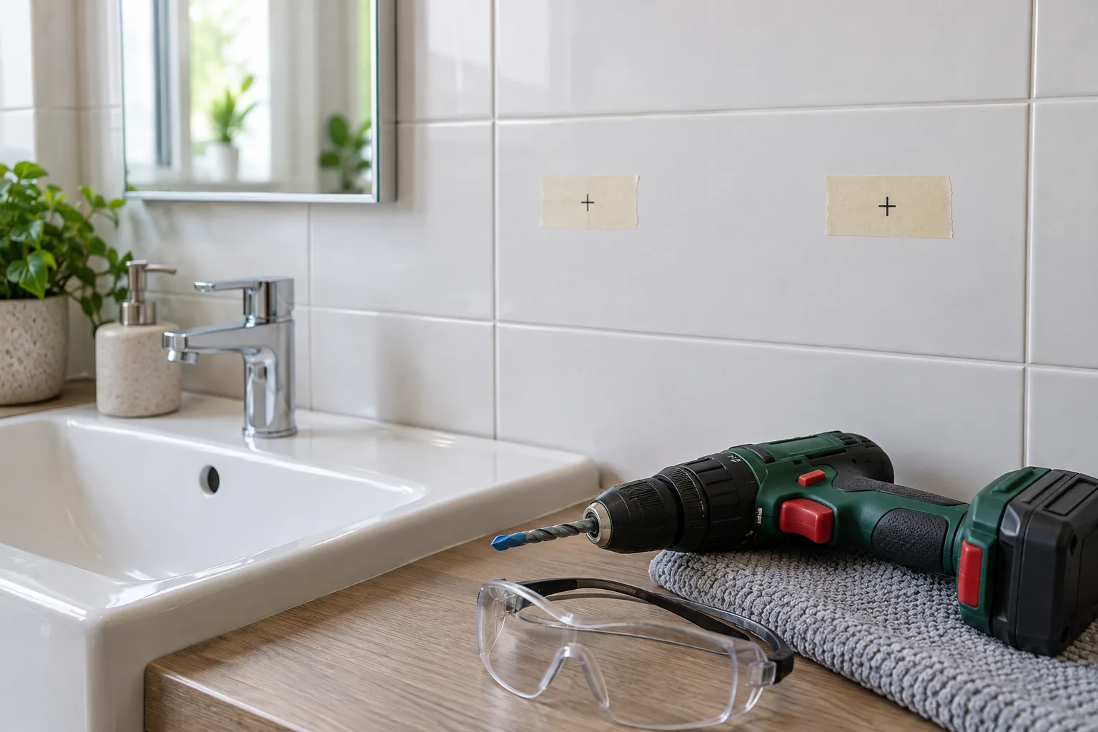
Glazed ceramic tile is hard at the surface but brittle when struck or drilled near an unsupported edge. A clean hole depends on the correct bit, low speed and light pressure. The more important check happens before the drill starts: bathrooms and kitchens contain concealed water pipes and electrical cables that a tile surface does not reveal.
Confirm the tile type
This guide covers ordinary glazed ceramic wall tile. Porcelain, natural stone, glass and thick floor tile need different bits, cooling and techniques. A ceramic tile often has a coloured clay body visible at an unfinished edge; porcelain is denser and consistent through its thickness. If uncertain, test a spare tile or ask the supplier.
Do not experiment on irreplaceable decorative, glass, cracked or hollow-sounding tiles. Specialist drilling is sensible when the finish is costly or the fixing carries a grab rail, screen or other safety-critical load.
Choose the fixing position, not just the visible centre
Keep holes away from tile edges and corners where stress concentrates. Avoid existing hairline cracks and very narrow cuts. Check that the fitting’s cover plate will sit flat and that its screws land in sound backing rather than a grout void.
Use the fitting as a template, level it and mark centres on masking tape. The tape helps the mark stay visible but does not prevent cracking by itself.
Check behind the tile
Review plans and trace visible taps, valves, sockets, switches and radiator pipes. Use a suitable detector across a broad area, recognising that foil-backed board, metal studs, tile adhesive and wet walls can affect readings. Do not drill directly above, below or horizontally from an electrical accessory without understanding the likely cable route.
Pipes may run vertically to a shower valve or basin and can sit close behind plasterboard. If the route cannot be established, move the fixing or use a bathroom fitting professional. A detector is not permission to drill blindly.
Tools and materials
Safety glasses and suitable gloves
Variable-speed drill with hammer action switched off
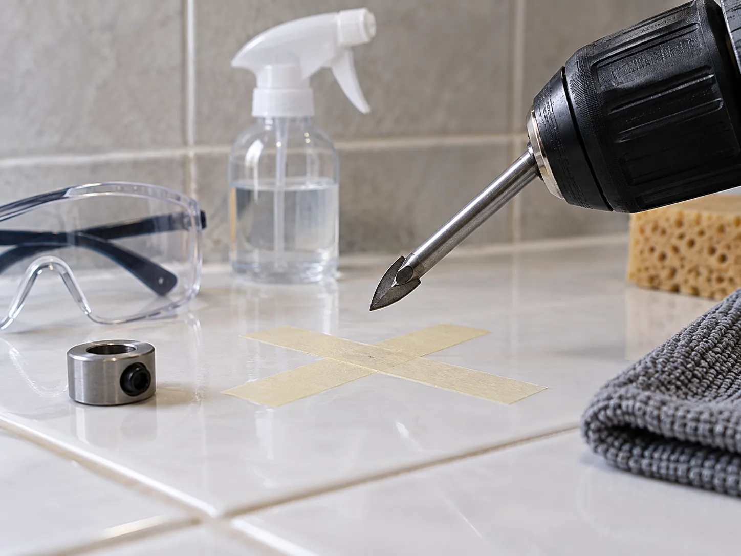
Sharp spear-point carbide ceramic-tile bit
Masonry or wood bit for the confirmed substrate behind
Masking tape, pencil, level and centre template
Depth stop or tape flag on the bit
Water spray for cooling where the bit maker recommends it
Fixing matched to the backing material and load
Practise on a spare tile
Support the spare fully on flat timber and rehearse starting the bit without skidding. Note the speed and pressure that produce powder rather than heat. Do not hold a loose tile in your hand or drill it over a void.
Step 1: make the surface safe and dry
Keep water away from sockets and powered tools. Dry the wall and floor, provide stable steps if needed and clear breakable objects. If cooling water will be used, choose a battery drill and apply only a small controlled amount at the bit, never a flowing stream.
Step 2: start slowly with no hammer action
Place the spear tip precisely on the mark, hold the drill square in both planes and run at low speed. Use very light pressure until the glazed surface is breached. A guide block or purpose-made suction guide can help on large smooth tiles. Do not centre-punch glaze.
Step 3: control heat and dust
Pause regularly and let the bit cool. Follow the bit manufacturer’s wet or dry instructions. Overheating dulls carbide and increases the force needed, which raises crack risk. Wipe slurry away so the hole remains visible, and never touch the hot tip.
Step 4: stop when the tile is penetrated
You will feel the resistance change as the bit reaches adhesive or the void behind. Stop and withdraw while rotating slowly. Do not continue deep into the wall with the tile bit. Vacuum the hole and reconfirm the substrate and safe depth.
Step 5: drill the backing separately
Change to the correct bit for known masonry, timber or board. Keep hammer action off until the ceramic is fully cleared; even then it may be unnecessary and can loosen tile adhesive. Use the depth stop so the hole is only as deep as the selected fixing requires.
Step 6: insert the fixing without stressing the tile
The plug should pass through the tile and expand in the backing, not inside the ceramic layer. Clear dust, seat it carefully and use a screw that matches the fixing. Tighten until the fitting is secure, using a protective washer where specified. Overtightening a small bracket can crack a tile hours later.
Common mistakes
Using hammer action on the glaze.
Drilling too close to a tile edge.
Using a blunt general-purpose masonry bit to start.
Applying body weight when the bit stops cutting.
Letting a wall plug expand in the tile itself.
Assuming a detector proves there are no pipes.
Overtightening the final screw.
If the glaze chips or a crack starts
Stop immediately and remove pressure. A tiny edge chip hidden by the bracket may be cosmetic, but a radiating crack can admit water and grow under load. Do not conceal a crack inside a shower area with the fitting. Replace or professionally repair the tile and inspect the backing.
Make a test record for repeated holes
For several brackets on the same wall, note the successful bit, speed, cooling method and measured depth from the first hole. Recheck for services at every position; a safe first hole does not prove the route is clear farther along. Replace a bit that has lost its sharp spear profile instead of increasing pressure to compensate.
Vacuum dust between holes and inspect the tile face under raking light. Fine cracks are easier to see before a fitting covers them.
When to avoid DIY drilling
Use professional tiling support for porcelain or glass you cannot practise on, suspected tanking close behind the surface, underfloor heating, large-format tiles with uncertain support, or safety-critical fittings. Any uncertainty about electrical cables belongs with a qualified electrician.
For an accessory with failed fixings, the guide to repairing a loose towel rail shows how the wall material and bracket load affect the next step.
Let the substrate carry the load
For a small accessory where the wall build-up and service route are already known, an experienced handyman can choose the correct tile bit and substrate fixing.
The tile is a finish, not the main fixing material. Drill its glaze slowly, stop at the backing and then use a fixing designed for the wall and load. Accurate service checks and restrained final tightening matter more than speed.
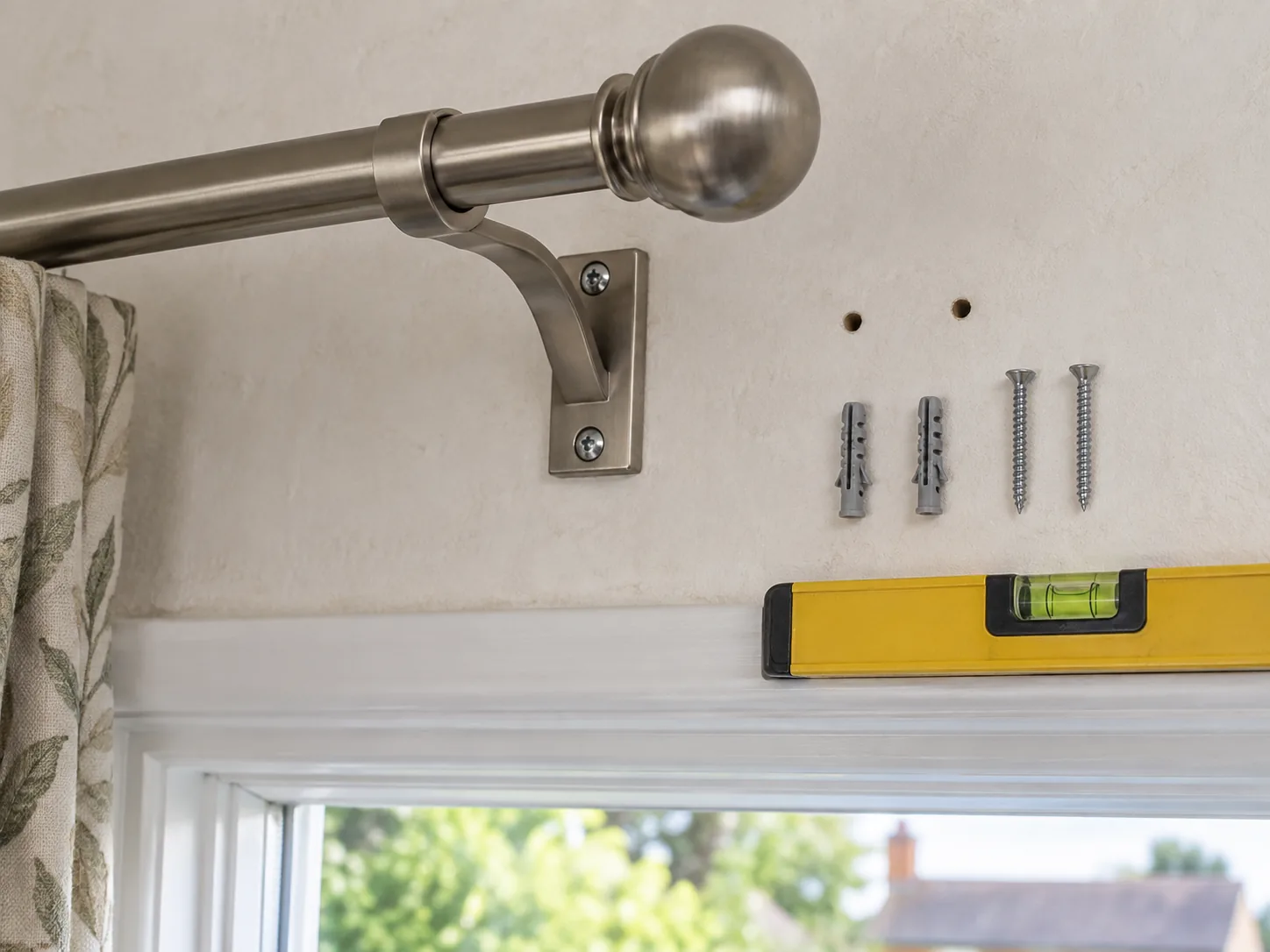
A curtain pole carries more load than its weight suggests. Heavy fabric creates leverage at the brackets every time the curtains open, and fixings above a window may meet lintels, hollow plasterboard or old crumbly plaster. The pole stays straight when the bracket layout, wall material and curtain load are considered together.
Measure the window and the curtains
Measure the opening at the top, middle and sill. Decide how far the pole should extend beyond each side so curtains stack clear of the glass. Confirm the finished curtain drop and where rings or eyelets sit relative to the pole. A radiator, deep sill or projecting handle may affect how far fabric must stand from the wall.
Check the pole’s maximum span and bracket spacing. Wide windows and heavy lined curtains normally require a centre support, but eyelet curtains must still pass or divide correctly. Follow the pole manufacturer’s limits rather than copying an existing lightweight rail.
Understand what is above the opening
A masonry wall may contain a concrete, steel or timber lintel immediately above the window. Dot-and-dab plaster can create a void before masonry. Stud walls need known timber or suitable cavity fixings. Old plaster may sound hollow while still covering solid brick.
Use construction information and a suitable detector to check for electrical cables and pipes. Cables can run vertically or horizontally from nearby accessories. Do not drill where the substrate or service route is uncertain; a curtain and blind fitting service can select an appropriate method.
Tools and materials
Stable steps, tape measure, pencil and long spirit level
Detector suited to cables, pipes and studs
Drill and bits appropriate for the confirmed substrate
Depth stop and vacuum
Fixings rated for the wall and curtain load
Screwdrivers and the complete pole kit
Low-tack tape and a straight timber batten for marking
Do not rely on the small generic plugs supplied with every kit. They may be unsuitable for your wall. Never stand on a chair or drill one-handed from an overreaching position.
Lay out bracket centres
Mark the centre of the window, then the left and right bracket centres at equal distances beyond the reveals. Choose a height that provides clearance above the frame and matches curtain length. Use a long level or laser to transfer a true horizontal line; ceilings and window heads are not always level.
Offer each bracket plate to the marks and ensure screw holes are not too close to a plaster edge. Check the pole will clear the window handle, vents and any blind. For three brackets, centre support alignment must allow the pole to sit naturally without being forced upward.
Test one position before drilling every hole
Run the detector across a broad area, not only the pencil mark. If it indicates a service or metal lintel, stop. Moving a hole a few millimetres may not make it safe because the hidden object continues behind the plaster. Specialist lintel drilling or an alternative mounting board may be required.
Drilling into known masonry
Start through plaster without hammer action to reduce breakout, then use the bit and setting appropriate for the masonry. Keep the drill square and control depth. Vacuum the hole so a plug can seat fully in solid material rather than remaining in soft plaster.
Use screws long enough to engage the rated plug but no deeper than safely planned. Tighten the plate firmly without crushing plaster or bending the bracket.
Fixing to plasterboard
Where possible, position brackets over verified timber studs or a planned timber pattress. For a cavity position, use a fixing whose load rating and board-thickness range suit the curtain and bracket leverage. Self-drilling plugs intended for light loads may not support wide, heavy curtains.
Do not place a cavity fixing into damaged board or too close to an opening edge. If the board flexes, several old holes overlap or the bracket base is small, install proper support through carpentry work.
Small areas of damaged plaster around abandoned holes should be made sound before decorating; the method in the guide to repairing plasterboard holes explains the preparation.
Step 1: install the outer brackets lightly
Fix both plates but leave final adjustment available. Place the empty pole in its cups and check level. Measure from pole to sill at both ends as a secondary check, recognising that the sill itself may vary.
Step 2: position the centre bracket from the pole
With a wide pole supported at both ends, bring the centre bracket up to it without lifting the pole above the level line. Mark, check for services again and fix. This prevents a centre support from introducing a visible hump.
Step 3: prepare the pole and rings
Cut a metal or timber pole only if the kit permits it. Measure between finials and account for any connector. Cut square with the correct fine-tooth blade, deburr metal thoroughly and keep swarf away from carpet. Place the required curtain rings on each section before fitting finials.
Step 4: tighten, hang and load gradually
Tighten bracket and cup screws evenly. Hang one curtain at a time while another adult supports the pole. Open and close slowly, watching for bracket rotation, plaster movement and rings catching at a connector. Stop if a fixing shifts.
Common mistakes
Using the window head as a level reference.
Omitting a required centre support.
Using generic plugs without identifying the wall.
Drilling near a detector signal.
Setting brackets too close to a reveal edge.
Forcing the pole into a high centre bracket.
Testing immediately with both heavy curtains pulled sharply.
Troubleshooting
The pole looks level but curtains hang unevenly
Measure the curtain headings and hooks, then check floor and sill levels. Do not tilt a secure pole to compensate for one curtain being hooked differently.
A bracket screw spins
Remove the load immediately. Do not fit a longer screw until the wall and service depth are known. Repair the substrate or select a rated fixing in a safe new position.
The centre joint catches rings
Check connector orientation and centre-bracket position. A single long pole or passing-ring system may be needed for curtains intended to cross the whole span.
Secure fixings come before a perfect line
Where the substrate is sound but the installation is awkward or high, a handyman installation avoids compromising bracket spacing simply to reuse old holes.
Measure from a true level, but choose positions that also offer sound support and avoid services. Correct bracket spacing, suitable fixings and gradual load testing give the pole a straight appearance that remains stable when the curtains are used every day.
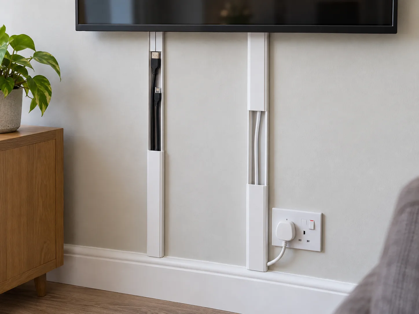
Surface trunking can make a wall-mounted television look tidy without cutting plaster or altering fixed wiring. The safe version of this project routes factory-fitted flexible leads to accessible sockets and keeps mains and signal cables organised. It does not involve putting an extension lead, plug or ordinary flex inside a wall.
Start with the equipment and connection map
List everything that connects to the television: mains power, aerial or satellite coax, HDMI, Ethernet, soundbar, games console and any USB accessories. Record which side each socket sits on and where the equipment will live. Check connector sizes; an HDMI plug needs more trunking space than its cable.
Allow slack for the TV to tilt or swing through its full bracket movement without pulling a connector. Cables must not cross sharp metal edges or become trapped between the bracket and wall. If the television itself is not yet secure, arrange correct TV mounting before cosmetic cable work.
Choose the safest power arrangement
Use an existing accessible socket and the appliance’s approved mains lead. Do not cut off a moulded plug to fit a small channel, splice a flex, or run an extension lead through a wall void. Do not conceal a multiway adaptor behind a television where it cannot be inspected and heat can build up.
If the nearest socket leaves an impractical route, a qualified electrician can install a correctly positioned outlet and test the circuit. That is fixed electrical work, not a trunking shortcut. Use professional electrical services.
Keep mains and signal routes separate
Mains flex and low-voltage data or AV leads should use separate trunking or a proprietary divided system designed for segregation. Separation reduces interference and avoids crowding. Never place loose mains connections inside the same channel as HDMI or aerial joins.
Where routes cross, keep the crossing brief and close to 90 degrees. Leave power connectors accessible for isolation. Follow equipment and trunking manufacturers’ bend-radius and capacity limits.
Tools and materials
Two suitable sizes of paintable PVC trunking or a certified divided system
Internal and external corners, end caps and flat bends
Tape measure, pencil and spirit level
Fine-tooth saw and mitre box
File or deburring tool
Fixings suitable for the known wall construction
Detector for likely cables, pipes and studs
Low-tack tape for trial layout
Plan the route before cutting
Use low-tack tape to mark separate vertical runs from the TV towards the media unit and socket. Keep the route clear of radiator heat, curtains, doors and furniture fixings. Avoid the recognised zones above, below and horizontally from electrical accessories because hidden fixed cables may be present.
A detector is an aid, not proof that a wall is empty. If the route requires drilling near a socket or you cannot identify the substrate and services, stop and use adhesive trunking approved for the wall finish or seek handyman help alongside any required electrician.
Step 1: disconnect and label every lead
Switch equipment off, unplug it and photograph the rear connections. Label both ends of signal cables. Support a tilting TV so it cannot move unexpectedly; do not remove it from the bracket alone if it is large or heavy.
Step 2: measure for connectors, not just cables
Lay the proposed bundle loosely inside a sample of trunking. The cover should close without pressure, and plugs must pass through corners or be connected after the base is fitted. Do not exceed the manufacturer’s fill guidance. Overfilled channel pops open and crushes cable insulation.
Step 3: cut and deburr the trunking
Measure each straight section twice. Cut the base and lid square in a mitre box and smooth sharp edges. Use purpose-made corners where they improve cable bend radius. Dry-assemble the route and check that lids can still be removed for future changes.
Step 4: secure the bases
Adhesive-backed trunking requires clean, dry, sound paint and may damage finishes when removed. Press it only after the layout is final. For mechanical fixing, locate services, drill only to safe known depth and use fixings suitable for the substrate. Do not route screws through the channel once cables are present.
Step 5: lay cables without tension
Place signal and mains leads in their separate routes. Keep natural curves at entry points and add no tight coils behind the TV. A short service loop may be secured to the bracket where its instructions allow, away from ventilation slots and moving arms.
Clip on lids progressively, checking no insulation is trapped. Fit end caps or bushings anywhere a cable exits a cut edge.
Step 6: reconnect and test before decorating
Reconnect labelled leads, plug directly into appropriate outlets and move the bracket through its range slowly. Test picture, sound, network and all sources. Feel for abnormal heat after normal operation, without touching live pins or opening electrical equipment.
Only paint trunking if the manufacturer permits it. Lightly prepare the surface as directed, keep paint away from lid joints and allow full drying before refitting cables if they were removed.
Common mistakes
Running an extension lead or plug inside the wall.
Cutting a moulded mains plug off.
Mixing mains and signal cables in undivided trunking.
Using a channel too small for HDMI plugs.
Drilling vertically above a socket without service checks.
Leaving no slack for an articulated bracket.
Blocking the television’s ventilation openings.
When surface trunking is not enough
A new socket, fused connection, hard-wired equipment or any change to fixed wiring belongs to a qualified electrician. Specialist help is also appropriate for fire-rated walls, chimney breasts, damp walls, rented homes with restrictions and routes crossing communal areas. Never trade electrical safety for an invisible cable.
Neat means accessible as well as hidden
If the route needs new supports above the screen, the guide to fitting a curtain pole explains the same principles of detecting services and choosing fixings. For unexplained electrical trips, stop rearranging leads and use the safe checks in the RCD troubleshooting guide.
Keep a simple connection diagram with the equipment manual. It saves pulling off every lid when a source changes and shows future occupants which route carries power.
A good surface route has adequate capacity, smooth exits, separate power and signal paths, removable lids and accessible plugs. Plan for the television’s movement and future cable changes. The result can be discreet without burying components that need inspection or turning decorative work into untested electrical installation.
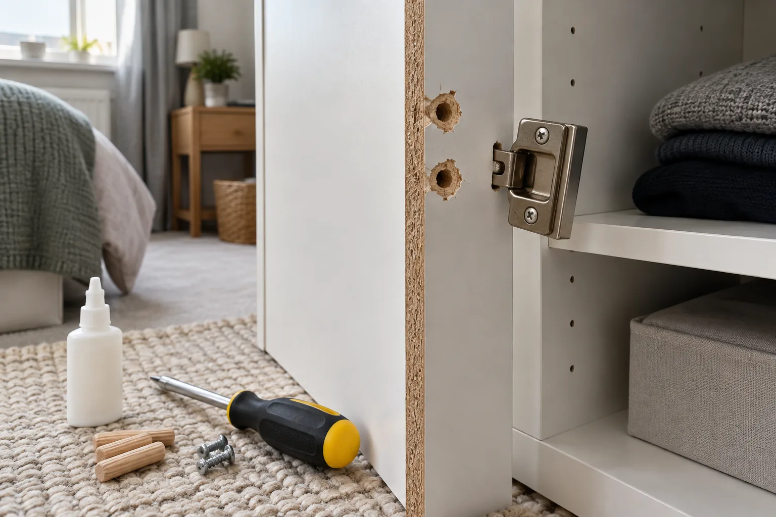
Flat-pack panels are usually chipboard or fibreboard faced with melamine or veneer. Once a screw pulls out, simply choosing a wider or longer screw can split the edge, pierce the opposite face or crumble more material. The correct repair depends on what the fixing carries: a light shelf clip, a cabinet hinge and an anti-tip bracket have very different safety demands.
Unload and support the furniture
Empty the affected cupboard or drawer. Support a loose door before removing its final hinge screw and ask another adult to handle tall or heavy panels. If the furniture is unstable, lay it down only when the instructions allow and there is space to do so without twisting the carcase.
A failed wall restraint is safety-critical. Do not use tall furniture until it is secured to an appropriate part of the building with fixings suitable for the wall. Repairing the furniture-side hole does not prove the wall fixing is safe.
Identify the material and fastener
Look at an unfinished edge. Chipboard shows coarse bonded chips; MDF has fine uniform fibres; solid wood has continuous grain. Note whether the original fastener is a confirmat screw, Euro screw, wood screw, cam dowel or machine screw into an insert. Photograph its length and location.
Measure panel thickness and use a depth stop for any drilling. Never assume the centre of a panel is clear: cam channels, dowels, glass, wiring for lights and fittings on the opposite face may be close.
Assess the damage
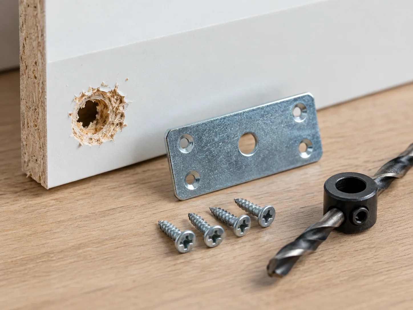
A clean enlarged hole with firm material around it may accept an insert or purpose-made repair. A crater that has broken through the panel face needs a plate or structural patch. Swollen, dark or soft chipboard has usually suffered moisture damage and will not hold a reliable fixing until the damaged area or panel is replaced.
Check why the screw failed. A misaligned hinge, overloaded shelf, sagging door or twisted carcase will pull out again if only the hole is treated.
Tools and repair options
Correct screwdrivers and drill with depth stop
Vacuum, masking tape and square
Manufacturer-approved replacement fitting
Purpose-made chipboard insert or threaded insert
Hinge repair plate for compatible concealed hinges
Hardwood dowel and suitable adhesive for selected non-critical holes
Short screws that cannot penetrate the panel
Do not use expanding foam, wall plugs cut at random, loose matchsticks or hard-setting filler for a load-bearing hinge. They can appear firm until repeated movement breaks the remaining board.
Option 1: use an unused hole in the existing fitting
Many hinges and brackets offer more mounting holes than were originally used. If the fitting can remain in exactly the correct position, a sound unused hole may accept the specified screw. Mark safe depth, drill the required pilot only if instructed, and keep well clear of the damaged crater.
This is not suitable when moving the screw would misalign a hinge plate, place it too close to an edge or leave the failed area unsupported.
Option 2: fit a hinge repair plate
A steel repair plate spreads the load across several new short screw positions and is often effective where a concealed-hinge plate has torn out. Choose a plate made for the hinge pattern and panel thickness. Dry-fit it so the door adjustment screws remain accessible.
Support the door, mark every hole, set a drill stop and make accurate pilots. Fix the plate flat without crushing the melamine, attach the hinge and adjust the door using the method in the cupboard-door alignment guide.
Option 3: install a purpose-made insert
Threaded or press-in inserts can restore a removable fixing when they are compatible with particleboard. Drill the exact diameter and depth stated by the insert maker, perpendicular to the face. Remove dust, install the insert without overtightening, and use the matching machine screw.
An insert near a panel edge can burst the side. Do not enlarge a hole unless there is enough sound material all around and no hidden cam or dowel channel.
Option 4: dowel a suitable low-risk fixing
For a non-safety-critical screw in sufficiently thick, sound board, a close-fitting hardwood dowel bonded into a clean cylindrical hole can provide new material. This is more controlled than packing the crater with splinters. Drill with a depth stop, glue the dowel, allow full cure, trim flush and drill a correct pilot.
Do not use this method for anti-tip restraints, beds, ladders, cot components or heavily loaded hanging cabinets. Seek furniture assembly or repair support.
Restore alignment before applying load
Loosely fit all related screws, square the cabinet and align the component before final tightening. Hinges should move without levering the plate. Drawer runners should be parallel, and shelf brackets must share load evenly. Tightening one fastener hard while the fitting is twisted starts the next failure.
Common mistakes
Using a screw long enough to exit the other face.
Drilling without a depth stop.
Filling the hole with soft wall filler.
Placing a new hole too close to a broken edge.
Ignoring a sagging door or twisted carcase.
Repairing only one of several loose hinge points.
Reusing a damaged cam fitting.
When the panel should be replaced
Replace or professionally reinforce a panel that is split through, swollen from water, crushed along an edge or missing a large area around a structural connector. The same applies when several attempted repairs overlap. Contact the manufacturer for a correct replacement panel where possible; its drilling pattern matters.
If an unstable unit must be disassembled, label every panel and fitting. Do not repeatedly tighten cams in crumbling board. A carpenter can make a stronger replacement where a proprietary part is unavailable.
Test with staged loading
After adhesives cure and alignment is complete, operate the empty door or drawer repeatedly. Add a quarter of the normal load, inspect the plate and panel, then increase gradually. Any fresh dust, clicking, movement or widening around a fixing means the repair is failing.
A strong repair uses sound material
A handyman repair is appropriate when the unit can be made safe with a recognised fitting and sound surrounding material.
The goal is to transfer load into undamaged board without creating a new weak edge. Measure panel depth, correct the alignment fault and choose a plate, insert or fitted timber repair designed for the job. When the component restrains a tall unit or carries a person, replacement or professional repair is the responsible choice.
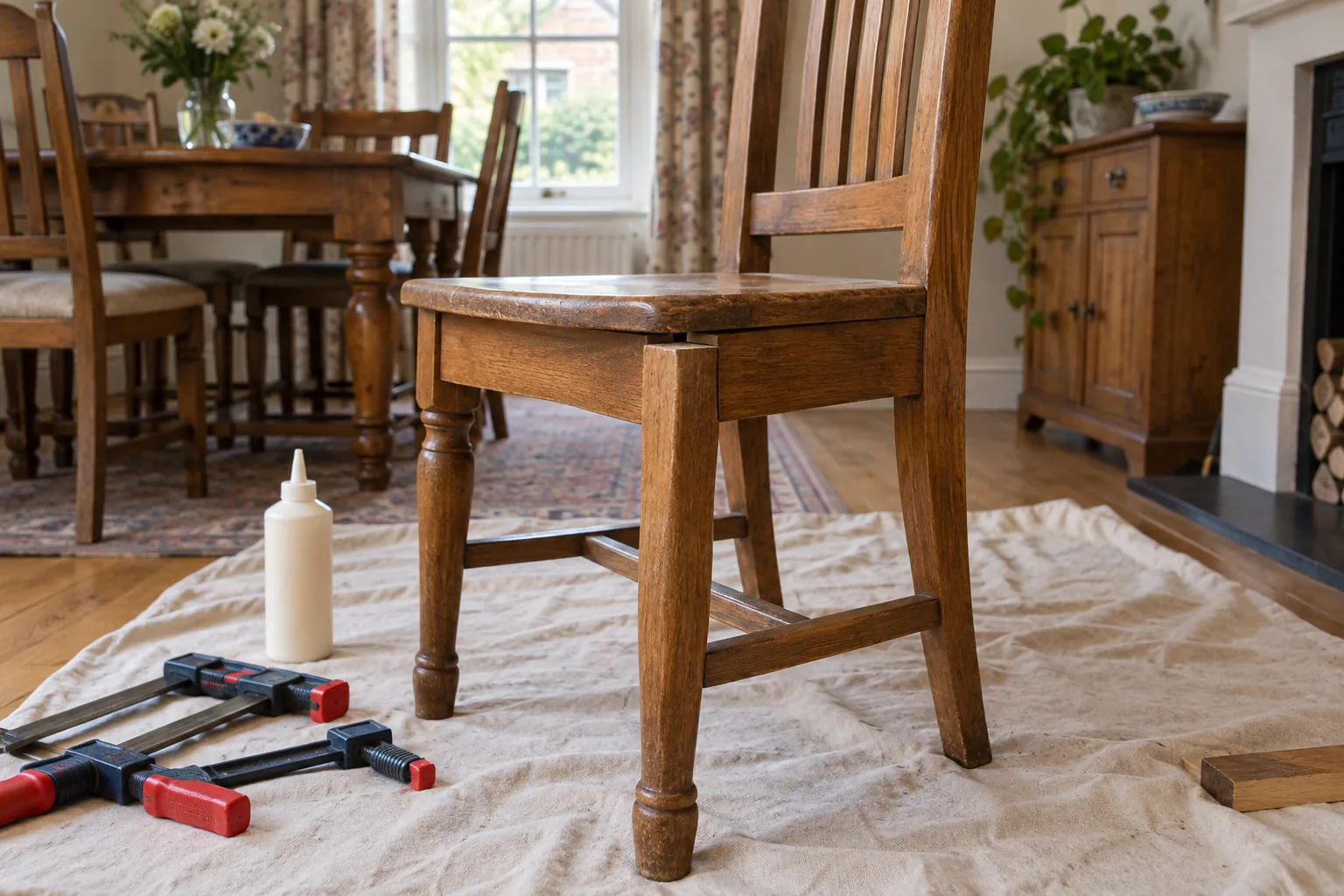
A chair can wobble because one joint is loose, several rails have worked free or a leg has split. Driving extra screws through the outside may stop movement briefly but can split the timber and weaken the original joinery. A sound repair finds the moving joint, removes failed adhesive and clamps the chair square while fresh glue cures.
Do not use the chair until it is assessed
Place it on a flat hard floor and remove any loose seat cushion. Press diagonally across the seat with your hands while keeping body weight off it. Watch each leg-to-seat and rail-to-leg joint. Mark movement with low-tack tape. A wobble caused only by one short leg is different from a joint that opens under load.
Stop if a leg is cracked along the grain, a joint has missing timber, the seat frame is split or the chair is valuable, antique or unusually constructed. Those repairs need professional furniture repair.
Identify how the chair is joined
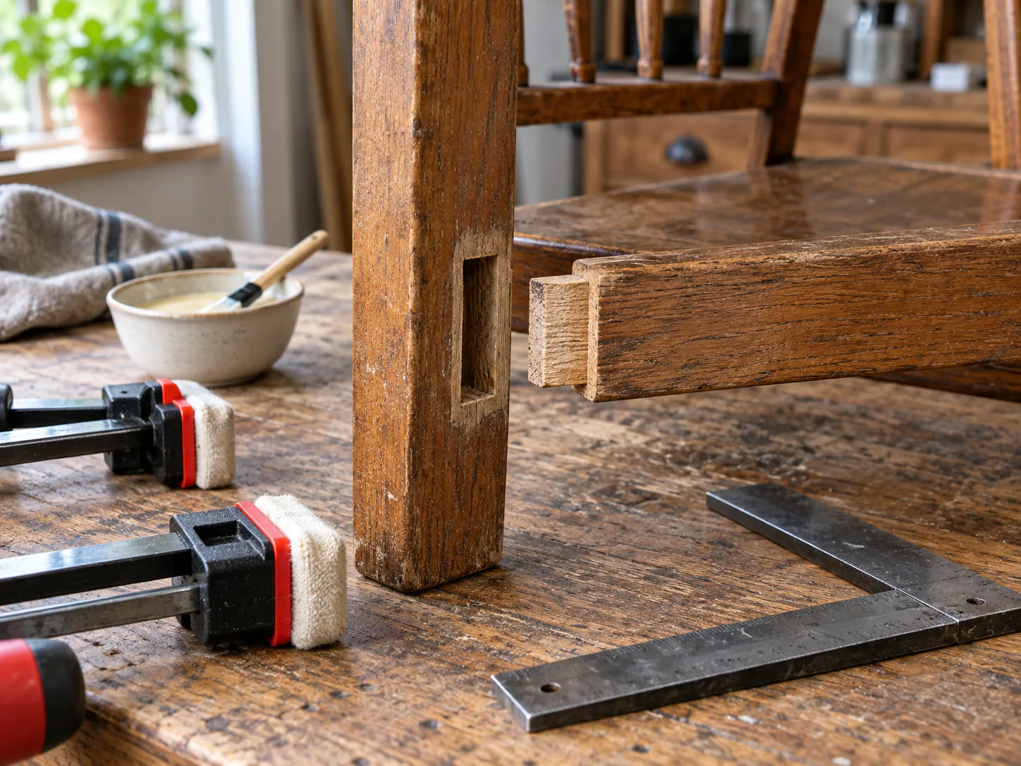
Traditional chairs often use mortise-and-tenon or dowelled joints. Modern furniture may use corner blocks, screws, cam fittings or metal brackets. Upholstery can hide structural fixings. Do not dismantle a joint until you understand how it was assembled and can return it to the same position.
Photograph all four sides and label rails discreetly with masking tape. Measure diagonals across the leg positions; matching measurements help confirm squareness during clamping.
Tools and materials
Woodworking clamps long enough for the chair
Padded blocks or clamp protectors
Soft-faced mallet
Scraper, small chisel and stiff brush
Good-quality wood adhesive suited to the timber and indoor use
Square, tape measure and damp cloth
Ratchet strap only where appropriate and used with corner protectors
Avoid expanding polyurethane glue as a substitute for a well-fitting joint; foaming does not restore missing wood. Do not inject glue into a closed joint and expect it to reach sound timber.
Decide whether partial dismantling is possible
A joint that opens several millimetres by hand may be separated carefully. Support adjacent rails and tap near the joint with a padded mallet, alternating sides. Never twist one rail as a lever. If the joint will not release with moderate controlled force, do not split the chair apart merely to add glue.
Several loose joints may need to come apart as one frame section. Label orientation and lay components in order. Photograph old wedges or pins before removal.
Step 1: clean old adhesive from mating surfaces
Fresh glue bonds to timber, not a thick skin of failed glue. Scrape softened residue carefully without reducing the tenon or widening the mortise. A joint that was originally hide-glued may require a conservation-compatible method. Keep sharp tools moving away from hands and finished edges.
Dry-fit the cleaned joint. It should enter fully with hand pressure or gentle mallet taps and have little side play. A loose tenon needs a fitted timber repair; filling the void with more glue will not make it structural.
Step 2: plan the clamps before gluing
Assemble the chair dry with pads and clamps in position. Check that pressure will close joints along their axes rather than bend rails sideways. Protect every finished surface. Measure diagonals and confirm all feet sit on a flat reference surface.
Work within the adhesive’s open time. If the whole frame cannot be aligned calmly before glue begins to skin, repair it in logical sections or seek carpentry support.
Step 3: apply a controlled film of glue
Coat both clean mating surfaces with a thin, even film, reaching the shoulders and sides without filling the mortise like a cup. Reassemble immediately and seat the joint fully. Wipe squeeze-out with a damp cloth while avoiding excessive water on old finishes.
Step 4: clamp square, not merely tight
Tighten clamps gradually in sequence. Watch each joint close and compare diagonals. Place the chair on the flat surface and confirm all four feet touch. Extreme pressure can bow rails, crush fibres and squeeze out too much adhesive; use only enough to close sound joints.
Step 5: allow full cure
Leave the chair undisturbed for the product’s stated clamp and cure times at a suitable room temperature. Do not “test” it by rocking before cure. Remove clamps, clean any remaining residue with a finish-safe method and inspect each shoulder for a complete closure.
If the chair still rocks on the floor
Move it to another known-flat surface. A rigid chair that rocks without joints moving may have unequal leg lengths or a twisted frame. Confirm the frame is square before shortening anything. Adding felt pads can compensate for a tiny floor irregularity but should not hide a structurally twisted chair.
Repairs to avoid
Driving long screws through legs into end grain.
Adding metal angle brackets where they split thin rails.
Pouring glue into a joint without cleaning it.
Using nails to pin a moving mortise-and-tenon joint.
Clamping so hard that rails bow.
Sanding or planing a leg before checking frame twist.
Sitting on the chair before the adhesive has cured.
When the joint needs new timber
A tenon that has lost material can be rebuilt or replaced, and a damaged mortise may accept a fitted insert. These are precise repairs: the grain direction, shoulder location and final dimensions carry the load. Screws, filler and glue-soaked sawdust are not equivalent. Chairs used by children, older people or anyone with limited mobility deserve a conservative safety decision.
Protect the finish during structural work
Old varnish, wax and painted surfaces can mark under clamps even when the pressure seems light. Use clean cork, leather or timber pads larger than the clamp jaws, and place protective film between squeeze-out and absorbent pads. Test cleaning methods out of sight. If the finish lifts, becomes cloudy or transfers colour to the cloth, stop before enlarging the damage.
Do not refinish the entire chair simply because one joint was repaired. Local colour matching and conservation of an aged surface may require specialist judgement.
If the chair came as a knock-down kit rather than traditional joinery, consult its instructions or use a furniture assembly service; proprietary bolts and inserts need a different repair from glued timber joints.
Prove the repair gradually
For chipboard or proprietary connector damage, use the separate guide to repairing flat-pack fixings. A sticking wooden drawer has different wear points, covered in the guide to checking drawer runners.
After full cure, press the empty chair diagonally and inspect the joints. Apply load gradually while another person watches for movement. Listen for clicks and recheck after several uses. A durable chair repair is quiet, square and supported by close-fitting timber—not by hidden excess glue or external hardware.
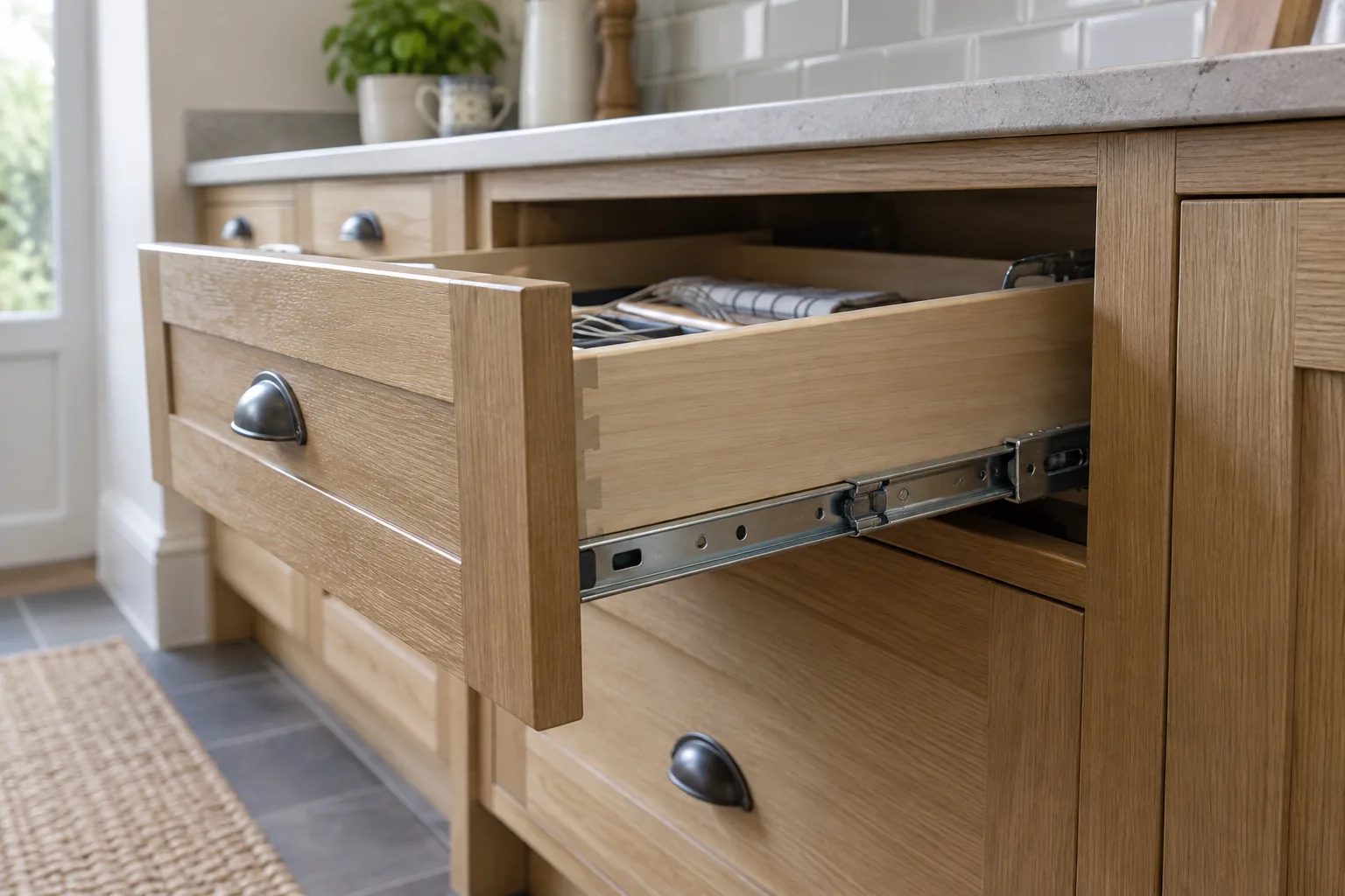
A drawer that sticks can be caused by a crumb in the track, a swollen wooden edge, a loose screw or two runners mounted at different heights. A drawer that comes off its slides may have a broken stop or incompatible replacement part. Diagnosis starts by unloading and identifying the runner rather than applying oil to everything that moves.
Make the drawer safe to remove
Empty it completely, including removable organisers. Support the front with both hands and extend slowly. Wide or heavy drawers need another adult. Do not let the drawer hang from one runner; this bends metal slides and tears screws from chipboard.
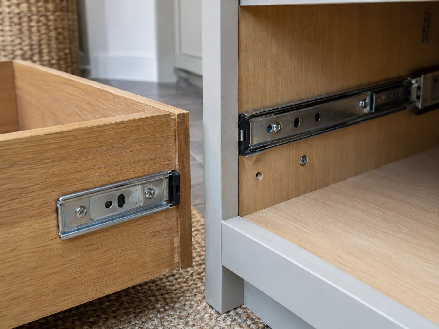
Side-mounted ball-bearing slides often have release levers, one lifting and one pressing down. Undermount runners may release with clips beneath the front. Wooden runners may simply pull to a stop and lift. Find the manufacturer’s method or inspect with a torch before forcing it.
Identify the failure pattern
Sticks at the same point: debris, bent runner or protruding screw
Front sits crooked: one runner loose or height adjustment changed
Drawer drops when opened: failed stop, clip or rear bracket
Moves in humid weather: timber swelling or tight clearance
Opens by itself: cabinet not level or slides misaligned
Scrapes the drawer below: overloaded base or loose front
Take photos of both sides while the drawer is still fitted. Compare screw positions, gaps and how far each slide extends.
Tools and materials
Correct screwdrivers and small socket set if required
Spirit level, combination square and tape measure
Vacuum and soft brush
Manufacturer-approved dry lubricant
Matching screws, no longer than the cabinet material safely allows
Timber dowel and wood adhesive for suitable solid-wood repairs
Replacement runner pair of the same type and length if damaged
Step 1: remove and clean
Place the drawer on a blanket. Vacuum crumbs from tracks and wipe metal slides with a dry cloth. Remove sticky grease with a mild compatible cleaner and dry it fully. Do not flush ball-bearing runners with water or pack them with household oil, which attracts grit.
For traditional timber runners, look for a polished high spot where wood rubs. Do not plane it immediately; first confirm that the cabinet is square and the runner has not moved.
Step 2: inspect the drawer box
Check that the bottom remains in its grooves and the four corners are square. A bowed base can drag or overload the runners. Tighten accessible assembly screws by hand, but stop if they spin. Split timber, a separating front or loose dovetails need furniture repair before the drawer is reloaded.
Step 3: inspect runners and cabinet fixings
Extend each runner independently. It should move through the same stages without grinding, missing bearings or side-to-side looseness. Confirm that every mounting screw is flush; a proud head can catch the moving member. Check rear brackets for cracks.
Measure from a fixed cabinet reference, not the floor, to the front and rear of each runner. They should be parallel, level with one another and set back equally. Use slotted mounting holes for small adjustments before drilling anything new.
Step 4: repair a loose screw hole appropriately
In sound solid wood, an enlarged hole can often be drilled cleanly and glued with a close-fitting hardwood dowel. After full curing, trim flush and make a pilot hole for the correct screw. Do not rely on toothpicks for a heavily loaded runner.
Chipboard needs a purpose-made repair insert, a suitable larger fixing within the safe material depth, or relocation to an unused runner hole. A screw that is too long can pierce the cabinet side. If several holes have broken away, reinforce or replace the panel through carpentry work.
Step 5: realign before fully tightening
Loosen runner screws only enough for movement. Set both slides parallel and at matching heights, then tighten one front and one rear fixing on each side. Refit the empty drawer and test. Adjust in millimetres until the front gaps are even, then secure the remaining holes specified by the runner manufacturer.
Step 6: replace damaged slides as a pair
Match runner length, extension, load rating, side clearance and fixing pattern. Replacing only one worn slide can create unequal resistance. Mark the original reference lines, fit cabinet members square and attach drawer members at identical positions.
Soft-close mechanisms often need an exact compatible pair. Do not bend catches or remove damping parts to make a mismatched runner fit.
Traditional wooden drawers
After alignment and cleaning, a small amount of plain candle wax or a furniture-approved dry lubricant can reduce friction on bare wooden runners. Keep wax away from surfaces due to be painted or glued. If timber has swollen from damp, correct the humidity source and allow it to stabilise before shaving an edge.
Plane only a clearly identified high spot, taking very fine cuts and testing often. Removing too much creates a drawer that rattles in dry weather.
Reinstall and test progressively
Engage both runners at the same time and push until release catches lock. Open and close the empty drawer ten times, checking the front gap and listening for contact. Add half the normal load and repeat before fully loading it. Heavy pans and tools may exceed a domestic runner’s rating even when the drawer fits.
Common mistakes
Lubricating dirt instead of cleaning the track.
Supporting a drawer on one extended runner.
Using longer screws without checking panel thickness.
Adjusting one slide without measuring the other.
Replacing only one runner from a matched pair.
Planing swollen timber before the room dries.
Testing immediately with the full load.
When the cabinet is the problem
Several drawers drifting open, uneven gaps across the whole unit or runners repeatedly loosening can indicate an unlevel cabinet or failed carcase joint. Check that wall and floor units are securely installed. Do not remove structural cabinet fixings or disturb nearby plumbing to chase drawer alignment.
For a newly built unit, revisit the assembly sequence before altering parts; a correctly completed furniture assembly should leave the carcase square and both runners on matching references.
Clean first, compare both sides and repair the supporting material rather than simply tightening a spinning screw. When runners are sound, parallel and correctly loaded, the drawer should travel evenly and remain captured through its full extension.
Floor sanding removes only a thin layer of timber, so preparation is not simply moving furniture. Protruding metal can tear abrasive belts and throw sparks, loose boards can split, and historic repairs may conceal pipes or cables just beneath the surface. A careful survey gives the sanding contractor clean access while preserving boards that may be difficult to replace.
Agree the scope before touching the floor
Ask the contractor what they expect the room to contain, whether they will punch nails, fill gaps, replace boards, remove finishes and apply the final coating. Confirm who moves appliances, doors and radiators. Some sanders prefer to inspect every fixing before the homeowner carries out minor work.
Discuss the intended appearance. Deep black staining, worm trails, wide gaps and old patches will not necessarily disappear. Sanding cannot make thin, cupped or heavily damaged boards new, and excessive material removal shortens their life.
Identify the floor construction
Original pine boards often span joists, with a void containing electrical cables, heating pipes and sometimes ceilings directly below. Later boards may sit over chipboard, concrete or previous flooring. Lift nothing until you understand the likely direction of joists and service routes.
Check whether the visible boards are structural or decorative overlay. Thin engineered timber and wood-effect laminate require different treatment and may not tolerate conventional sanding. If uncertain, ask a floor-sanding specialist to identify them.
Look for moisture before planning a finish
Search for dark edges near external walls, staining around radiator valves, musty odour, soft fibres and boards that have swollen together. Resolve plumbing, damp or ventilation faults and allow the timber to stabilise. Sanding damp wood clogs abrasives and can expose a clean surface that later moves or discolours.
Where a leak has affected the structure, arrange water-damage assessment. Do not rely on surface dryness alone; a contractor may use a moisture meter to compare areas.
Plan for dust, noise and curing time
Modern extraction reduces dust but does not eliminate it. Empty adjacent open shelving, close internal doors and discuss sealing routes to the rest of the property. Arrange access, parking and electrical supply with the contractor. Finishes can require hours or days before socks, furniture, rugs or pets are allowed back.
Remove curtains or tie them well above floor level. Take pictures, lamps and fragile objects from walls because vibration can move them. Protect smoke alarms only in the manner agreed for the work, and restore them immediately afterwards.
Clear the room completely
Move furniture, rugs, floor lamps and loose cables to another room. Do not stack belongings in one corner; edge sanding needs the full perimeter. Heavy pianos, built-in cupboards and connected appliances require a separate plan rather than last-minute dragging.
Lift removable door stops if they obstruct sanding, label them and store their screws. Ask whether doors need taking off. A door may no longer clear after underlay or thresholds change, so record existing gaps.
Inspect every board in strong light
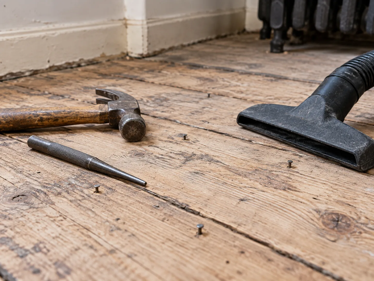
Vacuum first, then walk slowly in soft shoes. Mark protruding nails, screws, splinters, rocking ends and previous filler with low-tack tape on the skirting, not directly on fragile finish. Press boards with body weight; do not stamp. Listen for movement and note exactly where it occurs.
Deal with exposed metal carefully
Old cut nails, modern screws, carpet staples and broken tacks all damage sanding equipment. Remove surface staples and stray carpet pins with appropriate pliers while protecting the timber. Existing board nails are usually punched a few millimetres below the planned finished surface, but only after checking the board is supported.
Never drive a nail or screw where the service route is unknown. A fixing that has risen may have been selected to avoid a pipe. If you did not install it and cannot verify below, mark it for the contractor instead. Loose boards belong with careful carpentry repair.
Do not lift boards casually
Old boards can split at the tongue, edges or nail holes. Levering from one point damages the face that sanding is meant to preserve. If access is essential, identify services, cut paint at edges, work across several joists and use proper lifting tools. Replacement timber should match thickness, species and moisture condition as closely as practical.
Decide how gaps will be treated
Narrow seasonal gaps may be left open. Wider gaps can be filled with timber slivers, flexible products or resin-and-dust systems depending on construction and movement. Ordinary decorator’s filler becomes brittle and drops into the void. Expanding foam restricts movement and looks poor.
Agree the method before sanding because slivers and repairs may need fitting first, while fine filler often follows an initial sanding pass. Ventilation requirements must not be compromised by indiscriminately sealing a suspended timber floor.
Check edges, thresholds and hearths
Remove carpet gripper rods and sharp pins where the whole room is changing to timber, but confirm the final junction detail first. Protect stone hearths and tile edges. A loose doorway profile should be repaired using the threshold-strip guide or removed for planned replacement.
Final checklist for the day before
Room empty from wall to wall
Known damp sources resolved and timber condition agreed
Loose boards and metal fixings marked
Service routes disclosed to the contractor
Pets, children and valuables kept away
Access, sockets, waste and parking agreed
Finish colour, sheen and cure restrictions confirmed
Ventilation and overnight security planned
Common preparation mistakes
Leaving furniture in the centre of the room.
Punching every visible fixing without checking below.
Filling moving gaps with rigid decorator’s filler.
Assuming dark stains will sand out completely.
Washing boards immediately before the visit.
Ignoring curing time when planning furniture return.
Removing historic boards without labelling their positions.
Preparation protects more than the sanding belt
Give the contractor a written note of every marked concern so useful information is not lost when protective tape is removed or dust extraction begins.
A clear room, dry timber, documented service routes and properly assessed fixings let the contractor concentrate on an even surface rather than emergency repairs. Mark uncertainty instead of hiding it. The best preparation preserves original material and makes the final finish predictable.
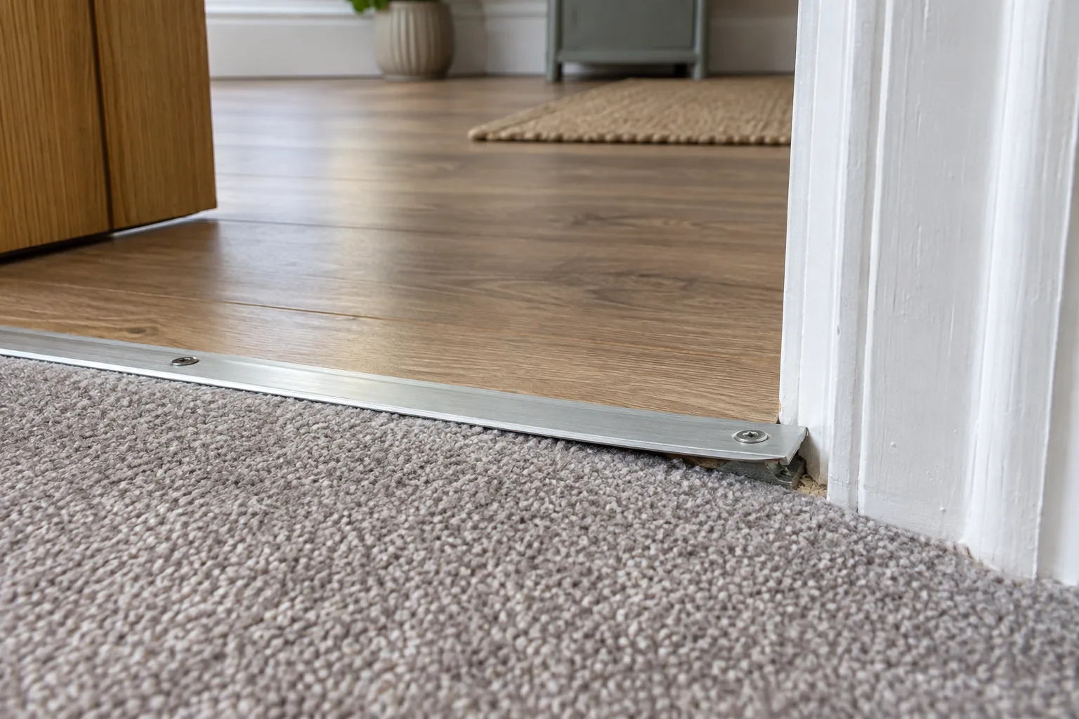
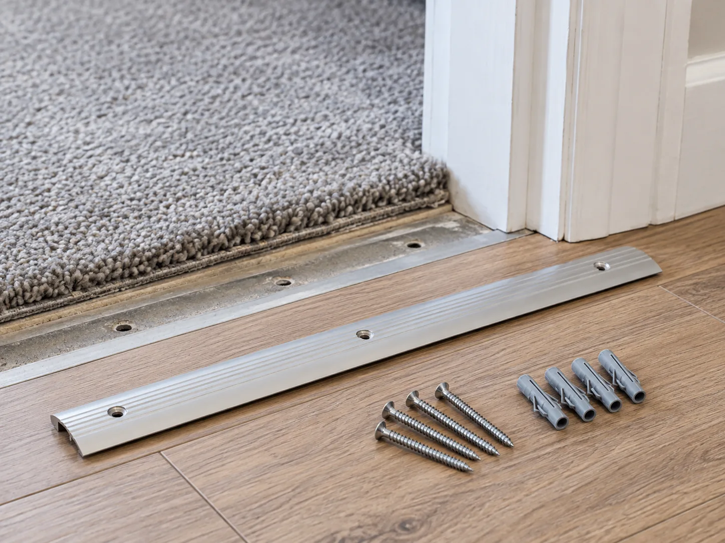
A loose threshold is more than a rattle. A raised end can trip someone, cut bare feet or let carpet and floating flooring move at the doorway. The lasting repair depends on the profile: some strips screw through the face, some clip into a base track, and others rely on adhesive. Forcing the wrong type down with longer screws risks hidden pipes, cables or underfloor heating.
Make the doorway safe first
Remove loose screws that could catch a foot and mark the area until repair. If the strip has a sharp or bent edge, lift it only if its fixing method is clear; otherwise cover the hazard temporarily with a rigid protector. Do not use loose tape across a busy doorway as a long-term measure.
Identify what the strip is doing
A transition profile may bridge equal-height finishes, ramp between different levels, cover a floating-floor expansion gap, grip carpet, or form part of a fire or acoustic detail. Photograph both sides and note the floor materials. The replacement must preserve the required movement and cover.
Lift one loose end gently. Visible countersunk screws indicate face fixing. A domed cover that springs from a rail is a clip system. No visible fasteners may mean adhesive or concealed clips. Do not prise against the decorative edge of laminate or tile.
Find out why it became loose
Screw holes have enlarged in timber or screed
Plastic plugs are the wrong diameter or depth
A clip rail has cracked or been fitted unevenly
Adhesive was applied over dust, polish or damp
The strip is too short and fixings sit close to its ends
Floor movement repeatedly pushes against the profile
A door catches and levers the strip upward
Correct the cause before refixing. A door that rubs may need the checks in the rubbing-door guide. A nearby open laminate joint should be assessed with the laminate-gap method.
Tools and materials
Eye protection, vacuum and pencil
Screwdrivers and correct replacement screws
Detector suitable for pipes and live cables
Drill and bits matched to the known subfloor, if drilling is safe
Correct plugs or timber repair material
Manufacturer-approved grab adhesive for an adhesive profile
Fine metal saw and file if a replacement needs cutting
Before drilling: identify the subfloor and services
Remove the profile and inspect existing holes. Timber, concrete, screed and tile require different fixings. Never assume a shallow floor is clear: heating pipes and electrical cables can cross doorways, and underfloor heating may lie immediately below the finish. Use drawings and an appropriate detector, but recognise that detectors have limits.
If the route cannot be established, reuse sound existing holes with the correct system or choose an approved adhesive profile. For uncertain floors, engage a flooring professional rather than drilling exploratory holes.
Method 1: refix a face-screwed strip
Vacuum the holes and test the strip’s alignment. Replace missing or damaged countersunk screws with the same diameter and an appropriate length. In sound timber, a slightly larger approved screw may hold; a badly stripped hole needs a proper timber repair, not several matchsticks in an unknown floor.
In masonry, replace spinning plugs with the correct type only after confirming safe depth. Seat every screw loosely, then tighten from the centre outward. Heads must finish flush so they do not catch feet, but overtightening bends the metal and pins floating laminate.
Method 2: repair a clip-in profile
Inspect the base track. Straighten only minor deformation; replace cracked clips or a twisted rail. Secure the track using its specified fixings and keep it centred over the expansion gap. Position the cover and press or tap it through a protective block in the sequence given by the manufacturer.
A clip profile that repeatedly releases may be the wrong height for the two floor finishes. Do not pack it with random offcuts. Choose the correct ramp or multi-level profile.
Method 3: rebond an adhesive strip
Scrape old adhesive from the subfloor without damaging floor edges, then vacuum and degrease with a product compatible with both surfaces. The base must be dry and firm. Dry-fit the strip, mask its position and apply only the adhesive specified for the profile and substrate.
Weight it evenly without blocking the doorway unsafely and leave it untouched for the full cure time. Excess adhesive should not bridge a floating-floor expansion gap.
Check carpet and laminate edges
Carpet backing should remain secured on the correct gripper or clamp, with no sharp pins exposed. Do not stretch carpet using the threshold as an anchor unless the system is designed for that purpose. Laminate needs concealed expansion space and must slide beneath or beside the profile as specified.
Cutting and fitting a replacement
Measure between the door stops at floor level and account for the profile’s end shape. Mark with a square, cut with the suitable fine-tooth blade and deburr every edge. Keep fixings away from the extreme ends, and check that the closed door clears before drilling or bonding.
Common mistakes
Using longer screws without checking for services.
Driving a screw through floating laminate.
Bending a strip down over an incorrect floor-height change.
Bonding onto dust, damp or floor polish.
Leaving proud screw heads.
Covering exposed carpet gripper pins rather than repairing the edge.
Ignoring the door that catches the profile.
Test the finished transition
Walk across from both directions in normal footwear, press each edge and listen for movement. Open and close the door fully. The strip should not flex, rock or produce a sharp lip, and the adjoining floating floor should retain movement space. Recheck fixings after several days of traffic.
Vacuum the joint during routine cleaning instead of flooding it with water. Early movement, a dark damp line or a returning click should be investigated before the holes enlarge again.
A secure strip still allows each floor to work
For damaged door edges or an opening that has moved out of square, use a door repair service. A handyman can handle a straightforward replacement where the subfloor is sound and the hidden service route is known.
The goal is not merely to clamp the doorway harder. Identify the profile, repair its base, protect hidden services and preserve the carpet grip or laminate expansion detail. When the floor build-up or service route is uncertain, replacing the transition professionally is safer than escalating screw length.
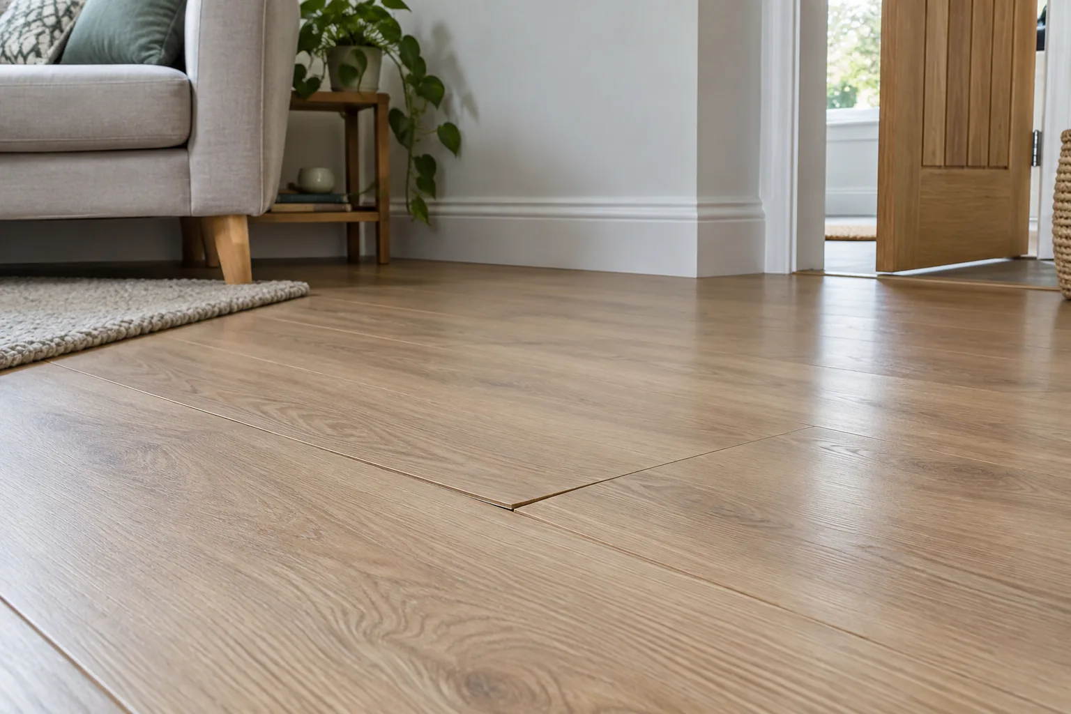
A narrow gap at the end of a laminate board can sometimes be closed without lifting the floor. Before moving anything, find out whether one plank has slid, several joints are separating, or the whole floating floor is trapped against a wall. Pulling a board into place without correcting the cause usually transfers the gap to the next joint.
Identify the type of opening
End-joint gaps run across the short ends of boards and often appear when a row shifts under repeated foot traffic. A long-edge gap may indicate an unlocked click joint, subfloor movement or damaged tongues. A raised ridge, tenting or boards pressed hard against skirting point to inadequate expansion space and should not be pulled tighter.
Check the floor in daylight from several angles. Mark the gap width with removable tape and inspect adjoining rooms, thresholds and heavy fitted units. Photograph the pattern before attempting a repair.
Look for moisture and temperature causes
Laminate changes dimension with indoor conditions. A recent leak, very dry heating season or rapid humidity change can expose joints. Check for swelling, dark edges, musty odour and soft underlay. Water-damaged high-density fibreboard rarely returns to its original shape and should be assessed through water-damage repair.
Do not close gaps while the floor is still wet or the room has just undergone a major humidity change. Find and repair the moisture source first, allow conditions to stabilise, and follow the flooring manufacturer’s stated environmental range.
Check whether the floor can move
A floating laminate floor needs a continuous expansion gap around walls, pipes, door linings and fixed objects. Skirting or beading hides this space but must not clamp the boards. Look beneath removable threshold trims and at radiator pipes. Kitchen islands and built-in wardrobes should not sit on top unless the floor system specifically allows it.
If the floor is trapped, free the obstruction before drawing a joint together. Cutting expansion space accurately can require removal of trims and specialist tools; use flooring support where edges are inaccessible.
Tools and preparation
Vacuum and thin plastic pick
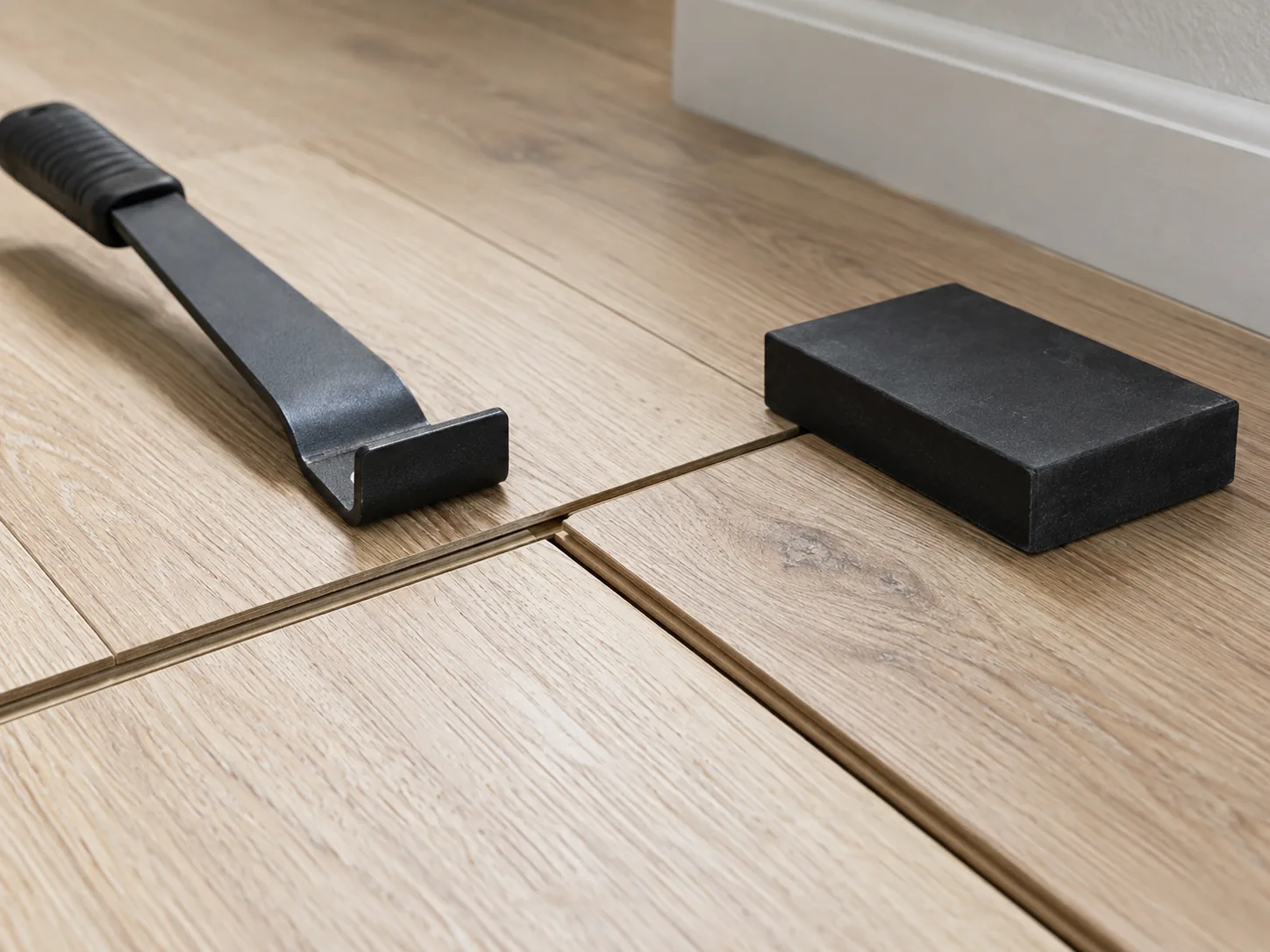
Purpose-made suction gap closer or clean rubber-soled pulling tool
Laminate tapping block and pull bar
Rubber mallet
Painter’s tape and pencil
Spare matching boards if available
Never strike the decorative edge directly. Steel hammers, screwdrivers and improvised adhesive tape can chip the wear layer or leave residue. Test any suction or friction tool on an inconspicuous area, particularly on textured finishes.
Step 1: clean the joint fully
Vacuum grit from the gap and use a thin plastic pick to remove compacted debris. Do not scrape the brown core or widen the edge. A tiny stone can prevent closure and crush the click profile when force is applied.
Step 2: trace where the movement can go
Follow the affected row towards both walls or thresholds. If one end gap has opened, closing it moves the plank and may open another joint. Decide which board needs to travel and confirm there is expansion space at the destination. Number several related gaps with tape so none is overlooked.
Step 3: move the loose plank gently
Attach the approved friction or suction tool near the centre of the board. Tap the tool lightly in the direction needed to close the joint, keeping force parallel to the row. Use many small taps and watch the decorative edges meet. Stop if the board bows, the long edge rises or the gap refuses to narrow.
Near a wall, removing the beading may allow a pull bar to engage the cut end. Protect the board with a manufacturer-compatible block and pull in small increments. Do not lever against plasterboard or skirting.
Step 4: inspect the closed joint
The surface should be flush and the printed bevel should form a consistent line. Run a fingertip lightly across it. A lip means the click profile has not engaged or is damaged. Do not hammer down on the face; lift and reassemble the row from an edge if the system requires it.
Should the joint be glued?
Most click floors are designed to remain unglued. Adding general-purpose adhesive can prevent future movement, swell the core and invalidate a warranty. Some manufacturers approve a specific joint adhesive for repairs, but use it only when their instructions explicitly allow it and the boards are dry and undamaged.
When boards must be lifted
Lift from the nearest free edge if several long joints are unlocked, the tongue has broken, or gaps immediately reopen. Label each row and board, remove skirting or thresholds carefully and follow the click angle specified for the product. Repeatedly flexing a joint can break it.
A damaged board in the middle of a large room may be reached by sequential disassembly. Cutting it out is an advanced repair that can harm underfloor heating or vapour layers. Professional laminate-floor work is safer where the build-up is unknown.
Common mistakes
Closing a gap without checking expansion clearance.
Striking a board edge directly with a hammer.
Filling the opening with coloured sealant or wood filler.
Gluing an unapproved floating joint.
Moving one plank and leaving a new gap farther along the row.
Ignoring swelling or moisture below the floor.
Pinning laminate beneath a threshold or fitted unit.
Monitor the repair
Leave the tape marks at the joint ends for a week and measure again after normal foot traffic. If the gap returns, note the room conditions and direction of travel. Repeated movement may be caused by a damaged lock, excessive run length, uneven subfloor or insufficient perimeter space.
Keep spare boards flat and dry rather than in a damp shed. A matching board from the same production batch can make a future replacement far less noticeable.
A successful local repair begins with a clean intact joint and a floating floor that is free to move. Close the gap with controlled force, inspect for a flush lock and track it afterwards. Where the core is swollen, the click is broken or the floor is trapped, replacing or relaying the affected section is more durable than repeated tapping.
Poor washing is often blamed on detergent when the dishwasher cannot circulate or drain water properly. A film of grease on the filter, blocked spray holes, a folded door seal or an incorrectly loaded tall plate can all reduce performance. Regular owner maintenance should clean accessible parts without opening the cabinet, pump or electrical systems.
Read the manual and let the machine cool
Filter locks, spray-arm clips and self-cleaning systems vary. Find the model instructions before pulling any part. Finish the cycle, switch off, unplug if the plug is accessible with dry hands, and allow hot components to cool. Turn off the local water valve if you will move the appliance, but routine internal cleaning should not require movement.
Stop and arrange dishwasher repair for burning smells, repeated electrical trips, damaged wiring, water below the cabinet or a door that will not latch securely.
What you need
Soft washing-up brush and old toothbrush
Warm water and mild washing-up liquid
Wooden cocktail stick or soft plastic pick
Microfibre cloths and an old towel
Torch and gloves
The manufacturer’s approved dishwasher cleaner if required
Avoid wire, sharp needles, abrasive powder and strong household drain cleaner. They can enlarge spray holes, damage stainless steel and seals, or leave hazardous residues.
Step 1: remove the lower rack and map the parts
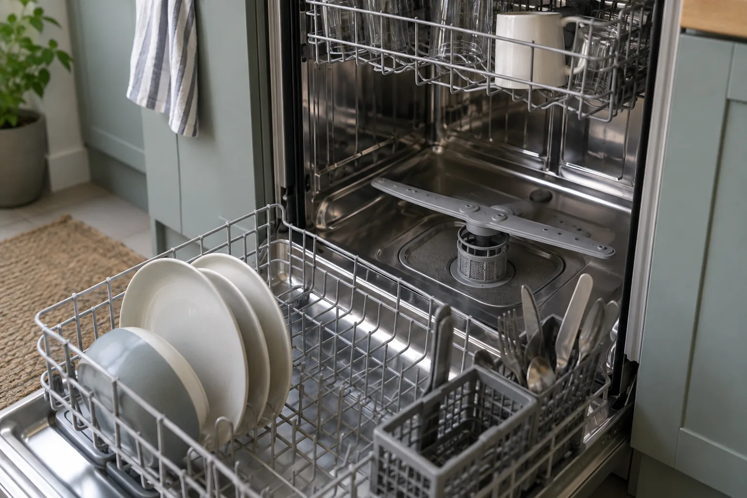
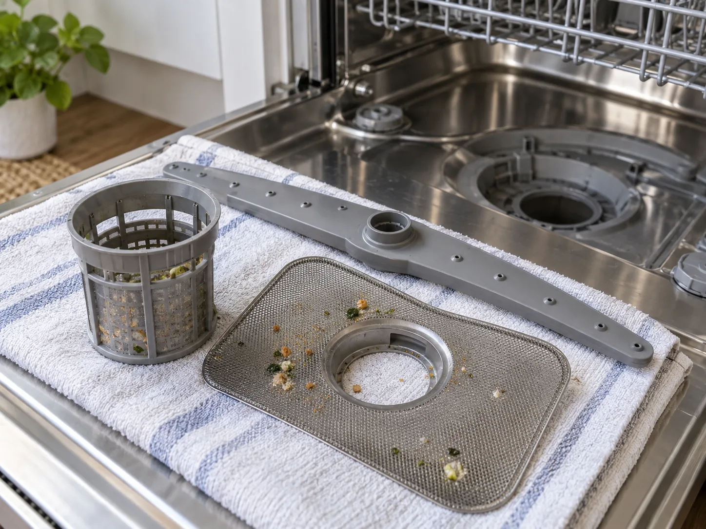
Slide out the lower rack and photograph the base. Identify the cylindrical filter, flat mesh, lower spray arm, salt cap and any covers that the manual names. Do not confuse the salt reservoir with a drain. Remove loose glass fragments with gloves, never bare fingers.
Step 2: lift out and wash the filter
Unlock the filter in the marked direction and lift it vertically so debris does not fall into the sump. Separate components only as instructed. Rinse under warm running water and brush both sides of the mesh. Pay attention to grease around the locking tabs.
Inspect for split mesh, distorted plastic and a damaged O-ring. A torn filter allows debris to reach the pump and must be replaced with the correct part. Wipe the accessible sump opening, but do not remove fixed covers or reach into the pump.
Step 3: clear the spray arms
Rotate each arm by hand before removal and note any contact with dishes or the rack. Release it according to the manual. Hold it under a tap and check that water exits all holes. Use a wooden or soft plastic pick to loosen visible particles, then flush them out rather than pushing them deeper.
Check the central bearing and seam for cracking. When refitted, the arm must rotate freely and sit at the correct height. A warped arm that strikes the rack should be replaced.
Step 4: clean the door seals and edges
Wipe the gasket with warm mild solution, working into folds without pulling it from the channel. Clean the lower door edge and hinge area where residue collects outside the main wash. Inspect for splits, hardening and a section that will not remain seated.
Do not coat the seal with oil or petroleum jelly unless the manufacturer specifies it. A leaking door can also result from an unlevel appliance, damaged hinge, excessive foam or a spray arm directing water incorrectly.
Step 5: clean dispensers and rack tracks
Remove hardened detergent from the dispenser lip and confirm the lid opens freely. Wipe rinse-aid spills, which can create excess foam. Clear food fragments from rack wheels and tracks so the rack seats fully; a rack left forward can obstruct the door or spray arm.
Step 6: refit in the right order
Place the flat screen correctly, insert the filter and turn it until the lock marks align. An unlocked filter can lift during washing. Refit each spray arm and spin it through a full turn. Replace the rack and check that tall items cannot touch it.
Step 7: run a controlled test
Restore power and run the cleaning programme or an empty hot cycle only if the manual recommends it. Use an approved cleaner at the stated dose; never combine cleaning chemicals. Stay nearby at the beginning and end, then inspect the floor, door corners and cabinet sides for moisture.
Open carefully after the cycle because steam can burn. Confirm that water has drained from the sump to the normal residual level and that the filter remains locked.
Troubleshooting common symptoms
Food remains on the upper rack
Check the upper spray arm, confirm its water connection engages when the rack is pushed in, and avoid nesting bowls. Low water pressure or a failed circulation pump needs professional diagnosis.
Water remains in the base
A small designed amount can protect pump seals, but a deep pool with debris suggests drainage trouble. Check the filter and visible waste hose for kinks. If the connected sink is also slow, use the slow-draining sink checks. Do not pour drain cleaner into the dishwasher.
The door leaks only during a cycle
Stop the machine. Check for excess foam, an item trapped in the gasket and a spray arm split along its seam. A persistent leak may involve the inlet, pump or internal hose and needs appliance service.
Common maintenance mistakes
Running the machine without the filter locked in place.
Using metal objects to enlarge spray holes.
Pulling a fitted gasket out merely to clean it.
Mixing bleach, descaler and proprietary cleaners.
Ignoring small glass pieces in the sump.
Assuming more detergent cures poor circulation.
Moving a built-in machine without isolating services.
Choose frequency from use and evidence
Inspect the filter after a heavily soiled load and clean it at the interval in the manual. Hard-water homes may need approved descaling; soft-water homes may not. Scrape large food scraps, load so arms can rotate and replenish salt and rinse aid only as the appliance and local water conditions require.
Finish with rotation, lock and leak checks
Water backing up from the sink connection or leaking at the shared waste needs a plumbing check, not further cleaning inside the dishwasher.
Good dishwasher maintenance leaves the filter locked, both spray arms turning freely, the door seal clean and the floor dry after a test. If performance remains poor after those checks, further dismantling is unlikely to be useful or safe—record the symptoms and arrange a model-specific diagnosis.
To provide the best experiences, we use technologies like cookies to store and/or access device information. Consenting to these technologies will allow us to process data such as browsing behaviour or unique IDs on this site. Not consenting or withdrawing consent, may adversely affect certain features and functions.
Functional
Always active
The technical storage or access is strictly necessary for the legitimate purpose of enabling the use of a specific service explicitly requested by the subscriber or user, or for the sole purpose of carrying out the transmission of a communication over an electronic communications network.
Preferences
The technical storage or access is necessary for the legitimate purpose of storing preferences that are not requested by the subscriber or user.
Statistics
The technical storage or access that is used exclusively for statistical purposes.The technical storage or access that is used exclusively for anonymous statistical purposes. Without a subpoena, voluntary compliance on the part of your Internet Service Provider, or additional records from a third party, information stored or retrieved for this purpose alone cannot usually be used to identify you.
Marketing
The technical storage or access is required to create user profiles to send advertising, or to track the user on a website or across several websites for similar marketing purposes.